|
|
WAITERS LANDING GEAR CONTROLLER

Waiters Landing Gear Controller utilizes an industrial Programable Logic Controller (PLC).
It incorporates full control for Nose and Main gear with one switch (UP-OFF-DOWN), PLUS, it has built in alarming/warning for the Canopy and Gear systems.
CLICK HERE for more information on this controller.
INFINITY AEROSPACE LANDING GEAR
LAST UPDATE - 12 April 2007
The disclaimer - These notes are NOT blessed or endorsed by Infinity Aerospace . I supply these notes strictly as my observations and methods on how I performed the installation. If you find any errors in these notes, please fell free to provide me with a correction.
Over the next few weeks, I'll try and organize this page a little better and incorporate as many of my notes as I can.
WARNING - HANDLE WITH CARE
Once the gear set is completely installed, and all the bolts are tight, the Infinity gear is strong and robust.
HOWEVER - During the assembly and installation process, the gear should be treated as if were a very rare and fragile piece china, BECAUSE IT IS!!!
To avoid damage to the gear, linkage, mounts, actuators, etc, during assembly and installation, follow these rules.
1) DO NOT allow the gear to free fall, either UP or DOWN, gently raise or lower by hand.
2) ALWAYS block the scissors (I used a 2x4 about 18 inches long) so the gear cannot accidently retract. Especially while the plane is upside down.
3) DO NOT place any weight on the gear until it is fully assembled.
4) UNDER NO CIRCUMSTANCES, should the gear be tested or operated with hydraulic power unless the gear is completely installed and rigged.
Just in case it wasn't clear:
NO, NO, NO. DON'T DO IT, the gear MUST be flight ready, or damage WILL result.
a) The forward Centerspar mount plate is completely installed and the bolts tight (7).
b) The AFT trunion Wing Attach plate MUST be in place, with temporary wing bolts (2) in both holes, snug and holding it in place.
c) The Trunion pin must be secure, with the forward washer, nut and cotter pin installed.
d) The upper Scissor / actuator pivot bolt (1) is installed, tight and pinned.
e) The Scissor upper/lower half pivot bolt (1) is installed, tight and pinned.
f) The Scissor / Gear leg retaining ring (New style) MUST be installed.
g) The actuator bolts (2) are installed, tight and pinned
h) The actuator rodend locknuts are tight.
i) The Actuator/Front Plate pivot reinforcement mount bolts (2) are installed, tight and pinned.
O-RINGS
The gear set I'm installing is approximately 10 years old and is one of the first built by Infinity. I purchased my gear set from a person who "changed their mind". It had never been installed, and sat in storage for over ten years.
Although the o-rings showed signs of flattening from the long term storage, every leak that I found was ultimately attributed to something I did. Here are things that you must be careful of:
Here are the mistakes I made regarding o-rings:
 1) Paint over spray on any of the shinny rod or strut surfaces. As the rod or strut slide in/out, dry paint acts like sandpaper against the o-ring. These surfaces must be absolutely clean. When painting, make sure exposed struts and rods are masked off to prevent over-spray. After the paint dries, wipe the rods and struts and visually inspect for over spray.
2) When hose or pipe fittings are installed they'll naturally form a burr. Example: the fitting near the bottom of the gear leg that compresses the strut, When a fitting is installed, it will form a burr on the inside of the strut. During normal operation, o-rings do not pass over this burr, However, if the strut is later disassembled, this burr will cut the o-ring as the strut rod is slid out of the strut tube, theres no way to avoid this. After any disassembling, inspect to make sure any of the "inside" burrs are ground off with a dremel sanding disk. All o-rings that came into contact with the burr MUST be replaced.
And, here are a couple mistakes that I was aware of, and didn't make:
1) Paint over spray on any of the shinny rod or strut surfaces. As the rod or strut slide in/out, dry paint acts like sandpaper against the o-ring. These surfaces must be absolutely clean. When painting, make sure exposed struts and rods are masked off to prevent over-spray. After the paint dries, wipe the rods and struts and visually inspect for over spray.
2) When hose or pipe fittings are installed they'll naturally form a burr. Example: the fitting near the bottom of the gear leg that compresses the strut, When a fitting is installed, it will form a burr on the inside of the strut. During normal operation, o-rings do not pass over this burr, However, if the strut is later disassembled, this burr will cut the o-ring as the strut rod is slid out of the strut tube, theres no way to avoid this. After any disassembling, inspect to make sure any of the "inside" burrs are ground off with a dremel sanding disk. All o-rings that came into contact with the burr MUST be replaced.
And, here are a couple mistakes that I was aware of, and didn't make:
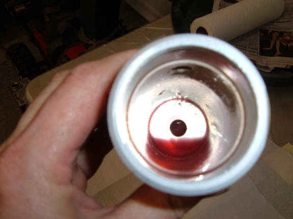
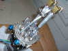
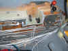
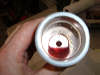 1) Installation cleanliness - I've had several people tell me they found metal debris when they disassembled their struts or actuators. This debris most likely chewed up their o-rings. I was very good about making sure all tubes and fittings were de-burred and blown out with an air hose before installing. Also, when it came time to fill and bleed the system, I initially flushed/bleed the system into an open container and inspected it for debris, I found none (ABOVE).
Generally, debris is a symptom of sloppy assembly on the part of the gear installer.
1) Installation cleanliness - I've had several people tell me they found metal debris when they disassembled their struts or actuators. This debris most likely chewed up their o-rings. I was very good about making sure all tubes and fittings were de-burred and blown out with an air hose before installing. Also, when it came time to fill and bleed the system, I initially flushed/bleed the system into an open container and inspected it for debris, I found none (ABOVE).
Generally, debris is a symptom of sloppy assembly on the part of the gear installer.
RESERVOIR FLUID OVERFLOWING
ANY AIR in the lines or actuators will tend to expand, and push fluid out the reservoir. This is especially noticeable when the gear is fully extended, as this is the point where the reservoir will be at its fullest. When the gear is fully retracted, the reservoir will be at its lowest level.
This will really be a mess after a CO2 bottle blow down as the lines will be full of CO2. The CO2 expands and pushes fluid into the reservoir. This CO2 "foam" seems like it lives in the system FOREVER. But after enough bleeding cycles, its ultimately removed.
I would recommend a full bleeding after any CO2 blow down. Believe me, it will take less time to redo a full bleed process, than it will to cycle the gear to perform the bleeding.
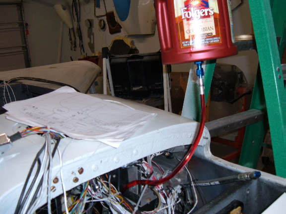
ALSO, leave the "Bleeding Reservoir" connected to the system as long as practical while the plane is in the shop.
 NOTE � Because my pump/reservoir is difficult to service because of its location, I plan on installing a small permanent �Overflow reservoir� near the nose hatch cover. Kind of like the overflow bottle on a car radiator.
GETTING READY TO BLEED THE SYSTEM
Review the BLEEDING instructions provided by Infinity Aerospace.
Make Bleeding Hoses and Tools:
 Make a "Bleeding Reservoir". This is a large container (2 or 3 quarts) that has an AN4 bulkhead fitting in the bottom. I drilled a hole in the bottom of the plastic coffee can, then installed an AN4 bulkhead fitting in the hole. I used an o-ring on the bulkhead fitting and nut so it wouldn't leak.
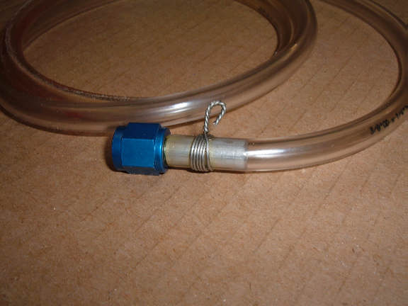
I then made three "Bleeding Hoses", These are clear plastic hoses, 4 or 5 ft long with AN4 fittings on them. Two of the hoses only need the AN4 fitting on one end. The third hose needs to have AN4 fittings on both ends.
Make a "Bleeding Reservoir". This is a large container (2 or 3 quarts) that has an AN4 bulkhead fitting in the bottom. I drilled a hole in the bottom of the plastic coffee can, then installed an AN4 bulkhead fitting in the hole. I used an o-ring on the bulkhead fitting and nut so it wouldn't leak.
I then made three "Bleeding Hoses", These are clear plastic hoses, 4 or 5 ft long with AN4 fittings on them. Two of the hoses only need the AN4 fitting on one end. The third hose needs to have AN4 fittings on both ends.
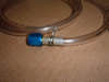 These can be made by flaring a 1/4 aluminum tube (1 or two inches long), install the flare sleeve and nut on the flared end, then slide the clear plastic tubing over the aluminum tube. Although the clear tubing should be a snug fit, a couple wraps of .032 safety wire around the plastic tube clamps it to the aluminum tube. There is no pressure applied to the "Bleeding Hoses". The clear plastic just allows us to see fluid / air inside the hose.
I have 4 AN4 caps and 4 AN4 plugs. Whenever I open a line, I always cap and/or plug it to minimize fluid loose and air from reentering the system
IMPORTANT BLEEDING NOTE - DO NOT open both the UP and DOWN lines at the same time while bleeding. The line you are NOT bleeding must be either capped, or remain connected to the actuator.
By the nature of the pumps design, If its pumping pressure out one line (i.e. UP), it ports (vents) the other line (i.e. DOWN) to the built in reservoir. If the vented line is uncapped, it could siphon and draw air from the line, rather than draw fluid from the "Bleeding Reservoir".
These can be made by flaring a 1/4 aluminum tube (1 or two inches long), install the flare sleeve and nut on the flared end, then slide the clear plastic tubing over the aluminum tube. Although the clear tubing should be a snug fit, a couple wraps of .032 safety wire around the plastic tube clamps it to the aluminum tube. There is no pressure applied to the "Bleeding Hoses". The clear plastic just allows us to see fluid / air inside the hose.
I have 4 AN4 caps and 4 AN4 plugs. Whenever I open a line, I always cap and/or plug it to minimize fluid loose and air from reentering the system
IMPORTANT BLEEDING NOTE - DO NOT open both the UP and DOWN lines at the same time while bleeding. The line you are NOT bleeding must be either capped, or remain connected to the actuator.
By the nature of the pumps design, If its pumping pressure out one line (i.e. UP), it ports (vents) the other line (i.e. DOWN) to the built in reservoir. If the vented line is uncapped, it could siphon and draw air from the line, rather than draw fluid from the "Bleeding Reservoir".
BLEEDING THE SYSTEM
Here�s what I do to bleed the system:
Remove the Reservoir VENT plug and fill the Reservoir as full as I can get it.
Do NOT reinstall the VENT plug. Instead, install an AN4 fitting where the VENT plug was located.
 NOTE: Tightening the fitting or vent plug, this may dislodge an internal vent tube inside the reservoir. See my notes on 27 Feb 2007 to show how I re-bent this tube and epoxed it so this cannot happen again. I don�t know what the exact purpose of this internal tube is, but I suspect it serves as an internal vent for an internal pressure relief valve.
I then used the "Bleeder Hose" with the AN4 fittings on both ends to connected the reservoir vent to the "Bleeding Reservoir".
Dump a quart or two of fluid into the "Bleeding Reservoir". NOTE: When cycling the gear normally, fluid may squirt out the "Bleeding Reservoir" fitting with such force as to spray the ceiling. I used an empty Dexron III fluid container to cover the AN4 fitting inside the "Bleeding Reservoir" to keep it from spraying.
Inside the wheel well, Remove the UP hose that feeds the actuator. Plug the actuator feed hose with a AN4 plug. Connect one of the �Bleed hoses� to the UP line that was supplying the actuator. Place the other end of the �Bleed hose� in a clean container to capture the fluid.
While watching the fluid level in the "Bleeding Reservoir", manually activate the UP pump for several seconds at a time by using a jumper wire to energize the pump solenoid. The short pulsing of the pump allows air bubbles to accumulate and push through the system.
ALSO, Keep an eye on the container at the wheel well so as not to overflow it.
Run about two quarts through the UP line.
Remove the AN4 plug and reconnect actuator feed hose to the UP lline.
Repeat this process for the DOWN line.
I reused the fluid that was pumped out at the wheel well, but only after straining it through a coffee filter. There should be no debris in the filter.
Reconnect the Actuator hose, then repeat this procedure for the other wheel well, both UP and DOWN lines
NOTE: Tightening the fitting or vent plug, this may dislodge an internal vent tube inside the reservoir. See my notes on 27 Feb 2007 to show how I re-bent this tube and epoxed it so this cannot happen again. I don�t know what the exact purpose of this internal tube is, but I suspect it serves as an internal vent for an internal pressure relief valve.
I then used the "Bleeder Hose" with the AN4 fittings on both ends to connected the reservoir vent to the "Bleeding Reservoir".
Dump a quart or two of fluid into the "Bleeding Reservoir". NOTE: When cycling the gear normally, fluid may squirt out the "Bleeding Reservoir" fitting with such force as to spray the ceiling. I used an empty Dexron III fluid container to cover the AN4 fitting inside the "Bleeding Reservoir" to keep it from spraying.
Inside the wheel well, Remove the UP hose that feeds the actuator. Plug the actuator feed hose with a AN4 plug. Connect one of the �Bleed hoses� to the UP line that was supplying the actuator. Place the other end of the �Bleed hose� in a clean container to capture the fluid.
While watching the fluid level in the "Bleeding Reservoir", manually activate the UP pump for several seconds at a time by using a jumper wire to energize the pump solenoid. The short pulsing of the pump allows air bubbles to accumulate and push through the system.
ALSO, Keep an eye on the container at the wheel well so as not to overflow it.
Run about two quarts through the UP line.
Remove the AN4 plug and reconnect actuator feed hose to the UP lline.
Repeat this process for the DOWN line.
I reused the fluid that was pumped out at the wheel well, but only after straining it through a coffee filter. There should be no debris in the filter.
Reconnect the Actuator hose, then repeat this procedure for the other wheel well, both UP and DOWN lines
BLEED THE STRUT LINE.
At the base of the strut, remove the feed hose that compresses the strut. Cap the strut fitting with a AN4 cap. Using a AN4 bulkhead fitting, connect the strut feed hose to a "Bleeder Hose".
Using a jumper wire, electrically energize the strut solenoid. This routes the UP pressure to the strut when the pump runs.
While watching the fluid level in the "Bleeding Reservoir", manually activate the UP pump for several seconds at a time by using a jumper wire to energize the UP pump solenoid.
Run a quart of fluid through this line.
Repeat this procedure for the other gear leg.
This should complete bleeding, the only air in the system should be a small amount in the actuators. No big deal.
Although this procedure will get most of the air out of the system, the gear will still need to be cycled many times (50 - 75) before the reservoir level will stay relatively constant. The reservoir should Remember, The reservoir is at it fullest when the gear is fully extended, at
I leave the "Bleeding Reservoir" connected.
PUMP ELECTRICAL SUPPLY
I use two Starter solenoids from Aircraft Spruce, Part # 22735. One for the UP and one for the DOWN.
CAUTION � Starter Solenoids require a lot of current to energize them, 4 � 6 amps. This is beyond the capability of most circuits or switches. I use another relay to energize the starter solenoids. You can see the starter solenoids and the �Driver relays� in the photos under 4 March 2007.
ALTERNATE DOWN SOURCE
I wired a momentary contact switch (DPDT center OFF)) that is label �Emergency Gear Extend� on one side, and "Emergency Strut Extend" on the other.
The �Emergency Gear Extend� side of the switch is wired directly to the DOWN Pump solenoid AND the nose gear DOWN relay. If the controller takes a dump, I can use this switch to manually run the DOWN pump to lower the main gear (and the nose gear).
I wired the other side of this switch to energize the Strut solenoid at the same time it runs the DOWN pump. This allows me to use this switch to uncompress (extend) the struts.
Review the Wiring Diagrams. These are in a PDF format.
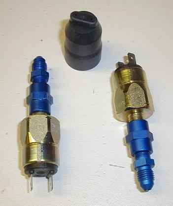
STRUT PRESSURE SWITCH
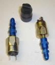
I didn�t like the Strut position switches used to indicate that the struts were retracted. Instead, I use a pressure switch to sense the strut compress pressure.
In the normal system, depending on the strut service pressure (60 � 100 psi) it takes about 800 � 1100 psi to fully compress the strut. I sense this pressure to indicate the struts are fully compressed and ready to retract the gear.
JD liked this idea and was thinking about incorporating it or suggesting it as an option in place of the two �strut switches�
I purchased this switch from Velocity Aircraft. Look under the retractable landing gear parts as a Pressure HI/LOW switch.
WAITERS LANDING GEAR CONTROLLER
I wasn�t satisfied with features on the original Infinity controller, so I designed my own. Its basically a very small industrial automation computer (PLC) that I programmed to behave exactly the way I want it.
Keep in mind that my controller does things slightly different than the Infinity controller. You can read about these by downloading the manual from my web site.
NOTE: I�ve been thinking about providing a much simpler design (smaller PLC). If there is enough interest in this, I may proceed with the project.
Review the contents of Waiter Landing Gear Controller. These are in a PDF format.
I hope this information helps. Again, good luck and welcome to the RG world.
In the early 1990's, Infinity put together a video of their newly released LongEZ Retractable Landing Gear set.
The video stars JD Newman, Founder of Infinity Aerospace, and co-stars Bill Theeringer and his O-235 powered LongEZ.
The Video includes footage from drop tests, gear swings, taxi testing, and flight testing. There is also a short segment near the end with a Cozy.
This video was digitized and compressed so it doesn't occupy to much bandwidth (30Mb). This means that it will be lower quality that the original VHS tape.
The video runs approximately 37 minutes (30Mb).
Contact JD at Infinity for a complete information package.
MAIN GEAR STRUT LEG, HOW IT WORKS
One of the unique features of the Infinity Gear is its ability to "RETRACT"
(compress) the struts prior to main gear retraction. On the LongEZ, this is important, otherwise the gear is to long and will not fit inside the wheel well.
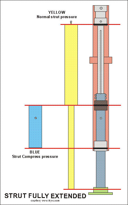
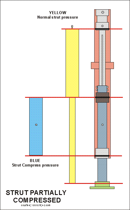
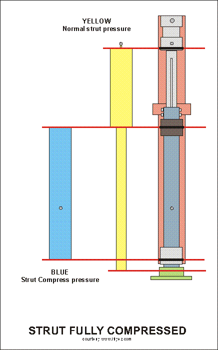 I've created these three drawings that illustrate the strut fully extended, partially retracted, and fully retracted.
By reviewing these drawings and comparing with the accompaning photos, you should be able to grasp a full understanding of how the Infinity Gear works.
There are three main components that make up the gear, The outside MAIN Gear tube (ORANGE in color), The upper guide (LIGHT GRAY in color), and the extendable STRUT Tube (BLUE GRAY in color).
To the left of the tube assembly I drew the two pressure "Compartments". If you overlayed these on top of the assembly drawing, this gives an idea of how the two pressure compartments are seperated, and how they expand and contract in order to extend/retract the strut tube.
The four red horizontal lines are drawn through o-rings that seal the two different compartments of the strut,
The "NORMAL strut pressure" compartment (I show this as YELLOW) and the "Strut Compress pressure" compartment (I show this as Blue).
Note that the red lines goes through an O-ring on the strut drawing. Althought the red line on the bottom doesn't appear to go through an o-ring, it does (not shown).
Inside the strut tube, a plug with an o-ring seal sits on the bottom against the foot. The inside (center) of the strut tube is at NORMAL pressure, and the outside of the tube is at COMPRESS pressure.
When the strut is properly serviced, the YELLOW pressure will be between 80-100psi. When it comes time to "compress" the strut.
Pressure is applied to the BLUE compartment. As the BLUE pressure builds up, it pushes the strut UP. (the blue compartment gets larger). It takes about 1,000 to 1,100 psi to hold the struts compressed. To Un-compress the strut, the BLUE pressure is relieved and the YELLOW pushed the strut back down.
I've created these three drawings that illustrate the strut fully extended, partially retracted, and fully retracted.
By reviewing these drawings and comparing with the accompaning photos, you should be able to grasp a full understanding of how the Infinity Gear works.
There are three main components that make up the gear, The outside MAIN Gear tube (ORANGE in color), The upper guide (LIGHT GRAY in color), and the extendable STRUT Tube (BLUE GRAY in color).
To the left of the tube assembly I drew the two pressure "Compartments". If you overlayed these on top of the assembly drawing, this gives an idea of how the two pressure compartments are seperated, and how they expand and contract in order to extend/retract the strut tube.
The four red horizontal lines are drawn through o-rings that seal the two different compartments of the strut,
The "NORMAL strut pressure" compartment (I show this as YELLOW) and the "Strut Compress pressure" compartment (I show this as Blue).
Note that the red lines goes through an O-ring on the strut drawing. Althought the red line on the bottom doesn't appear to go through an o-ring, it does (not shown).
Inside the strut tube, a plug with an o-ring seal sits on the bottom against the foot. The inside (center) of the strut tube is at NORMAL pressure, and the outside of the tube is at COMPRESS pressure.
When the strut is properly serviced, the YELLOW pressure will be between 80-100psi. When it comes time to "compress" the strut.
Pressure is applied to the BLUE compartment. As the BLUE pressure builds up, it pushes the strut UP. (the blue compartment gets larger). It takes about 1,000 to 1,100 psi to hold the struts compressed. To Un-compress the strut, the BLUE pressure is relieved and the YELLOW pushed the strut back down.
MAIN GEAR HYDRAULIC
Basic Hydraulic system
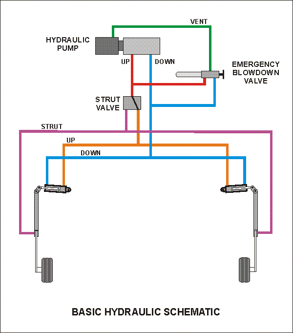
NOTE You can download a PDF file that containes all 7 hydraulic diagrams by clicking HERE.
The hydraulic system of the Infinity Gear consists of five major components;
1) Hydraulic Pump
2) Emergency Blow-Down valve assembly
3) Strut Valve
4) Main Gear ACTUATOR
5) Main Gear STRUT.
Refer to the "Basic Hydraulic Schematic".
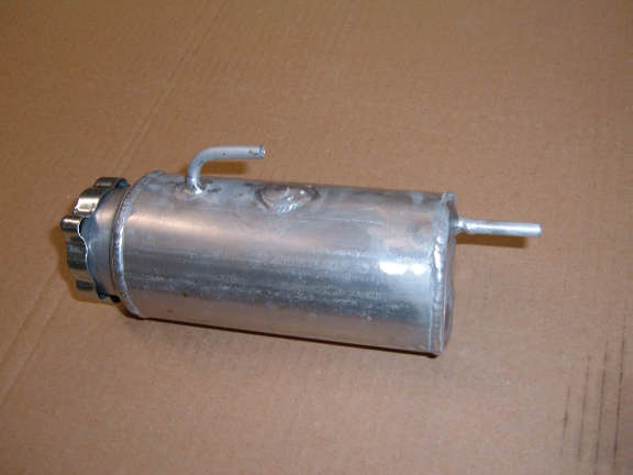
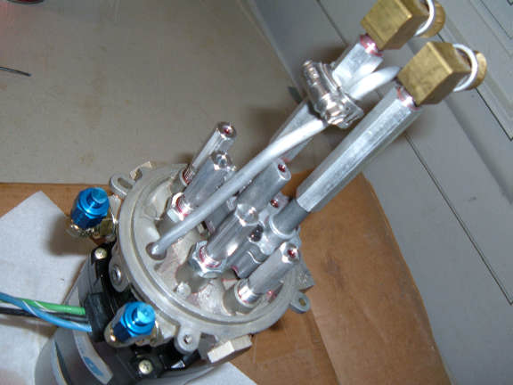
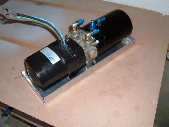
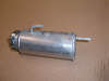
HYDRAULIC PUMP
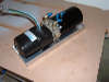
The Hydraulic Pump is a standard OilDyne pump Model # 108AM32GLB1HVT, is capable of work in either direction (up or down).
UP - When the pump runs in the UP direction, an internal regulator limits the pressure to approximately 1,400 psi. ALSO, while the pump is running in the UP direction, the DOWN line is internally vented into the internal reservoir.
DOWN - When the pump runs in the DOWN direction, an internal regulator limits the pressure to approximately 700 psi. ALSO, while the pump is running in the DOWN direction, the UP line is internally vented into the internal reservoir.
VENT - The pump has a built in reservoir. The reservoir has two fittings, one is used for the VENT return line for the Emergency Blowdown vaklve, and the other has a vnt filter installed so it vents to the atmosphere.
POWER - Power to the pump must be supplied through high current (50 amps) solenoids.
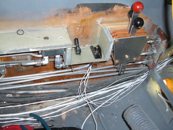
EMERGENCY BLOWDOWN VALVE
The Emergency Blowdown Valve has a manual handle used to actuate the valve.
As the handle is turned in by approximatly one turn, the UP pressure line is ported to the VENT line. As the handle is turned in approximately one more turn (two total), the CO2 bottle is punctured and expels its gas contents into the DOWN line.
NOTE: On the end of the Emergency Blowdown Valve is a fitting for the CO2 bottle. This fittling is ported directly to the DOWN line. DO NOT attempt to operate the gear (electrically or otherwise) unless a bottle is installed on the fitting.
STRUT VALVE
The strut valve is an electrically controlled valve.
In its NORMALposition, deenergized, the UP PUMP port is routed to the main gear UP ACTUATOR, the STRUT PORT is blocked.
When the strut valve is energized, the UP PUMP port is routed to the STRUT PORT, the UP ACTUATOR is blocked
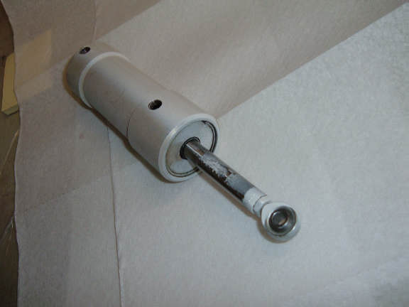
MAIN GEAR ACTUATOR
The Actuator piston is retracted when the gear is DOWN. The actuator piston is extended when the gear is UP.
MAIN GEAR STRUT
The Gear strut is normally serviced to 60 - 100 psi.
When hydraulic fluid is pushed into the bottom of the strut, the strut will compress.
I've had several questions from builders regarding the sequencing of the hydraulic system and what pressures should be seen during the different phases of extension and retraction.
I've included two time/pressure diagrams , one for normal RETRACT and one for normal EXTEND. The horizontal axis is time in seconds, the vertical axis is pressure in psi. There are also two bars above each chart that shows when the pump is running and when the strut solenoid valve is energized.
Click on each of the charts to open them on new pages, and print the charts.
IMPORTANT - The charts and descriptions are based on the use of Waiters Landing Gear Controller, and NOT the original Infinity Aerospace gear controller.
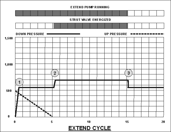
EXTEND
A quick description of what happens - When the gear is placed in the DOWN mode: (1) DOWN pump turns on, (2) when down pressure reaches 600psi, the strut solenoid is energized and a 10 second timer starts. When the timer completes (3), the strut solenoid is deenergized and the pump is shut off.
Extend Cycle - 1
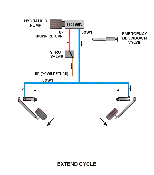 When the cycle starts (1), pressure in the DOWN line immediately jumps to about 500psi. Inside the pump, a relief valve is opened in the UP line and allows UP pressure to start bleeding off. As pressure on the DOWN side of the actuator cylinder builds and pushes the piston toward the down position, the movement of the piston also pushes the UP fluid out of the cylinder, through the tubing, into the pump, and out the relief valve into the reservoir. PLUS, The weight of the gear as it is swinging into the DOWN position also produces pressure in the UP line. The pressure attributed to the weight of the gear bleeds off as the gear nears a full DOWN position. (2)
Extend Cycle - 2
When the gear is fully down and the scissors are overcenter (2), pressure in the DOWN line builds up very rapidly (spikes). As the pressure passes through about 600psi, the Hydraulic Down Pressure switch tells the controller to energize the Strut Solenoid Valve. When the Strut Solenoid Valve energizes, the pressure that is holding the strut in a compressed position is released into the UP line.
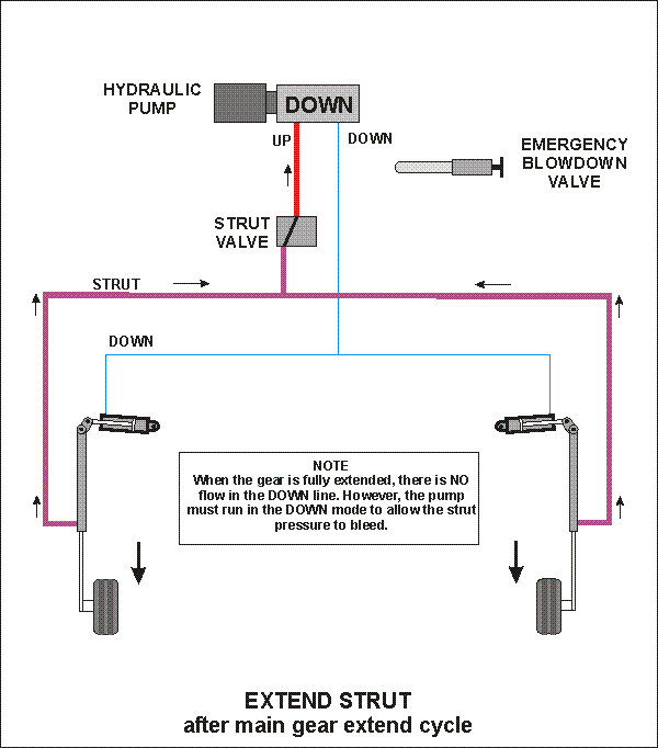 The pump doesn't "pump" fluid from the strut, strut fluid is forced out as the normal strut service pressure (i.e.100psi) pushes the strut down (extends it).
However, in order for the UP line pressure to be relieved into the reservoir, the pump must be running in a DOWN mode. Remember, the UP relief valve is located inside the pump. It's a mechanically operated valve thats actuated only when the pump motor runs in the DOWN direction. The DOWN portion of the pump has an internal bypass that is adjusted to approximately 700 psi so the pump doesn't stall while relieving the strut pressure.
The Strut Solenoid valve is on a timer that runs 10 seconds (3)
The pump doesn't "pump" fluid from the strut, strut fluid is forced out as the normal strut service pressure (i.e.100psi) pushes the strut down (extends it).
However, in order for the UP line pressure to be relieved into the reservoir, the pump must be running in a DOWN mode. Remember, the UP relief valve is located inside the pump. It's a mechanically operated valve thats actuated only when the pump motor runs in the DOWN direction. The DOWN portion of the pump has an internal bypass that is adjusted to approximately 700 psi so the pump doesn't stall while relieving the strut pressure.
The Strut Solenoid valve is on a timer that runs 10 seconds (3)
Extend Cycle - 3
When the 10 second timer times out, the Strut Solenoid Valve is deexergized and the hydraulic DOWN pump is shut off.
NOTE: When the gear is DOWN, the down pressure is constantly monitored by the Hydraulic Down Pressure switch. If the down pressure drops below 500 psi, the complete EXTEND CYCLE is initiated. (1) DOWN pump turns on, (2) when down pressure reaces 600psi, the strut solenoid is energized and the 10 second timer starts. When the timer completes, the strut solenoid is deenergized and the pump is shut off.

RETRACT
A quick description of what happens - When placed in the retract mode. The Strut Solenoid is energized at the same time as the UP pump is turned on (1), When the strut is fully compressed the strut solenoid valve is deenergized (2 & 3) the gear then retracts until pressure is built up (5).
Retract Cycle - 1
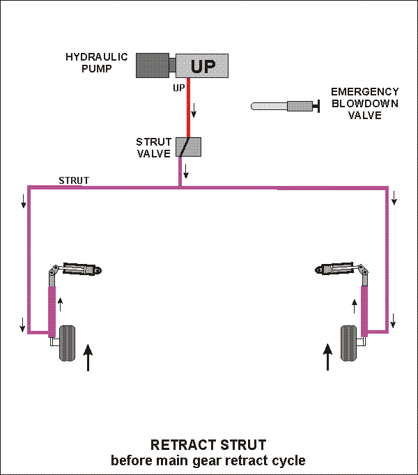 When the retract mode is entered, the Strut Solenoid Valve is energized at the same time as the UP pump is turned on. (1) The DOWN pressure is imediatly bleed off and the UP pressure rises very quickly to about 400 psi (depending on strut service pressure).
Retract Cycle - 2 & 3
Fluid is pumped into the strut to compress it. When the struts are fully compressed ( 900 psi. -depending on strut service pressure) (2) the UP pressure spikes to about 1,200 psi. (3). As the UP pressure passes through 1,100 psi, the Strut Pressure Switch signals the controller to deenergize the Strut Solenoid Valve (3).
Retract Cycle - 4
 When the Strut Solenoid Valve deenergizes, the 1,100 psi pressure is trapped in the struts and holds them in the compressed position.
At this time, the UP pressure now drops to 450 psi. (4). The UP pressure is now diverted to the UP actuator and the gear starts to retract. As the gear is swinging up, the weight of the gear causes the UP pressure to increase. (5)
When the Strut Solenoid Valve deenergizes, the 1,100 psi pressure is trapped in the struts and holds them in the compressed position.
At this time, the UP pressure now drops to 450 psi. (4). The UP pressure is now diverted to the UP actuator and the gear starts to retract. As the gear is swinging up, the weight of the gear causes the UP pressure to increase. (5)
Retract Cycle - 5
When the gear is fully retracted, the actuator stalls and the UP pressure spikes up very quickly. As the pressure passes through 600 psi, the Hydraulic UP Pressure switch signals the controller to turn the UP pump off.
NOTE - After the gear is retracted, both the Hydraulic UP Pressure Switch and the Strut Pressure Switch are continously monitored. If either of these pressures drop below their preset values, the Retract Cycle process will restart at (1)
EMERGENCY BLOWDOWN
The Emergency Blowdown valve allows for an alternate method of lowering the main landing gear in the event of an electrical failure
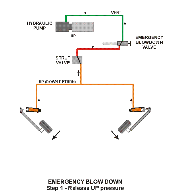
Step 1
As the handle is turned in by approximatly one turn, the UP pressure line is ported to the VENT line.
Step 2
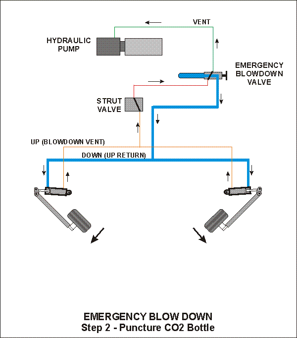 As the handle is turned in approximately one more turn (two total), the CO2 bottle is punctured and expels its gas contents into the DOWN line.
NOTE: On the end of the Emergency Blowdown Valve is a fitting for the CO2 bottle. This fittling is ported directly to the DOWN line. DO NOT attempt to operate the gear (electrically or otherwise) unless a bottle is installed on the fitting.
As the handle is turned in approximately one more turn (two total), the CO2 bottle is punctured and expels its gas contents into the DOWN line.
NOTE: On the end of the Emergency Blowdown Valve is a fitting for the CO2 bottle. This fittling is ported directly to the DOWN line. DO NOT attempt to operate the gear (electrically or otherwise) unless a bottle is installed on the fitting.
Waiters GPS Set Time program.
Waiters Flight Data Recorder.
Flight Data Recorder.
Recording aircraft flight data.
Aircraft Voice recorder.
Garmin GPS.
Garmin GPS Serial data Format.
Recording EFIS data.
Capture Serial data.
Convert Raw Data Files.
Free GPS Software.
Reading GPS data.
Reading Garmin GPS data.
Aircraft EFIS Flight Instruments.
Electronic Flight Instruments.
Aircraft Engine Monitor System.
Garmin G format.
Infinity landing gear LongEZ Plans Built Airplane.
Oil Heat system for Homebuilt airplane.
LongEZ Canard and main Wing.
Dynon instrument panel.
Custom Mouse cursors.
Garmin Serial Data Format.
Easy, Free Computer Time setting by GPS Receiver.
Custom mouse pointers.
Custom airplane mouse pointers.
LongEZ Nose gear doors.
Long-EZ main landing gear doors.
LongEZ grasscutter landing gear door.
Custom LongEZ mouse pointers.
Lycoming engine in LongEZ.
MT Propellor with 6 inch propellor extension.
EZNose Lift retractable nose gear for Long-EZ.
Rutan LongEZ is a plans built aircraft.
High speed homebuilt airplane.
Retractable landing gear for LongEZ.
Custom Airbus mouse cursor pointer.
Custom Velocity mouse cursor pointer.
NMEA 0183 Serial data Format.
Custom Cozy mouse cursor pointer.
Custom Aerocanard airplane mouse cursor pointer.
Custom E-Racer mouse cursor pointer.
Custom Canard airplane mouse cursor pointer.
Custom LongEZ mouse cursor pointer.
Set your Computer clock with this free GPS software.
Custom F15 mouse cursor pointer.
Custom A10 Warthog mouse cursor pointer.
LongEZ Hydraulic pump.
Retractable landing gear for a Long-EZ.
Custom F16 mouse cursor pointer.
Custom F14 mouse cursor pointer.
Custom Boeing 747 mouse cursor pointer.
Custom Boeing 767 mouse cursor pointer.
Custom Boeing 777 mouse cursor pointer.
Custom Boeing 737 mouse cursor pointer.
GPS Time Sync.
Custom Boeing 727 mouse cursor pointer.
Landing gear door rigging.
Custom Boeing 757 mouse cursor pointer.
Custom MD80 mouse cursor pointer.
Custom DC9 mouse cursor pointer.
Setting your computer to a GPS Time.
Custom RV mouse cursor pointer.
Downdraft cooling for LongEZ.
Speed brake installation.
Waiters Flight Data Recorder.
LongEZ Baggage pods installation instructions.
Waiters Custom Airplane mouse cursors.
Free GPS Time Sync Program.
LongEZ Intercom installation.
Major airframe overhaul of plans built EZ.
Weight and balance for a LongEZ.
Weight and Balance spreadsheet download for a Long-EZ.
LongEZ fuel system design.
How To remove the wings from a LongEZ.
How To remove the canard from a LongEZ.
Waiters GPS Time sync program runs on PC.
How To remove the engine from a LongEZ.
Long-EZ Downdraft cooling for a Lycoming O-320.
Long-EZ Wing Removal and installation instructions.
Waiters Retractable Landing Gear Controller.
Landing Light installation in LongEZ.
Install free EFIS software on your PC.
How to Put several longezs in one hangar.
How to install an Infinity Aerospace Retractable landing gear in a Long-EZ.
How to install DownDraft cooling on a Long-EZ.
GPS Time.
Setting you computer clock to GPS time.
How to set your Computer clock to GPS Time.
Using your GPS Receiver to set your computers clock.
Low cost GPS receiver used to syncronize Computer clock to GPS time.
Neat Canopy stay system for an EZ.
Cabin Heat using engine oil as source.
Waiters GPS Time, Syncronize your PCs internal clock with the GPS satellite.
Remote display of EFIS on a PC.
Cabin Oil Heater for a LongEZ.
LongEZ Landing Gear Door.
Rigging a LongEZ Landing Gear door.
Icom Radio in LongEZ.
How to Build a Manometer.
LongEZ Electrical system upgrades.
Grand Rapids EMS.
Custom Windows cursors.
Custom Windows mouse pointers.
LongEZ Cowling for downdraft cooling.
Record holding LongEZ flights.
Using a PLC for a retractable Landing Gear Controller in a LongEZ.
Syncronize your PCs clock to a GPS receiver.
Airspeed vs pressure lookup tables.
How to build a homebuilt airplane.
Video of LongEZ taking off.
Grasscutter landing gear door.
EZ Nose Lift installation.
Landing Gear status indicator.
Shareware software can set your PC clock vie a GPS receiver.
Landing Gear controller computer for LongEZ.
Landing gear doors.
Dynon EMS10 installed in instrument panel of a LongEZ.
Dynon EFIS D10A installed in instrument panel of a LongEZ.
Flight Data Recorder Software.
PlansBuilt LongEZ.
Video of High G turn in a Long EZ.
Strong Pitch Trim system installed in a LongEZ.
Strong Pitch Trim mounted on Left Side of Long-EZ.
Free software sets your PC clock with a GPS receiver.
Video of LongEZ Taking off.
Video of LongEZ Landing.
Video of LongEZ performing a high G turn.
Video of Infinity Landing gear being retracted into a LongEZ.
LongEZ Color White.
Painting your LongEZ.
White LongEZ.
Camoflage LongEZ.
Infinity Landing Gear for LongEZ.
Strong Pitch system.
|